What you will see
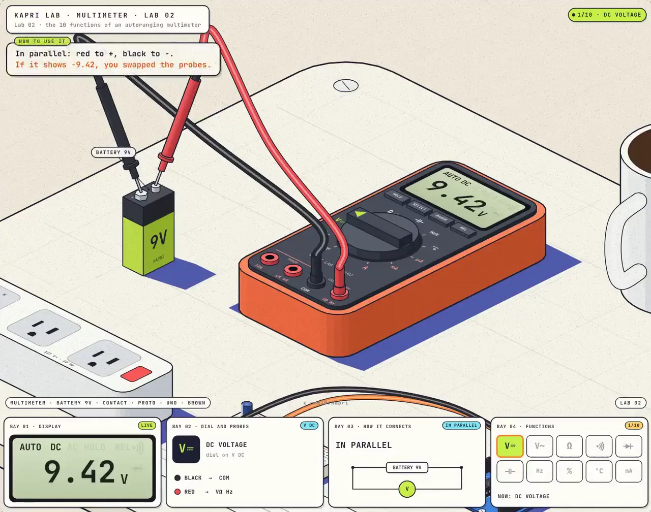
Each chapter is one function: DC and AC voltage, resistance, continuity, diode, capacitance, frequency, duty cycle, temperature and current. You pause, skip ahead and see which jack each probe goes into.
The readings are simulated with typical values. The 9 V battery reads 9.42 V, the wall outlet gives 127 V at 60 Hz, the red LED drops close to 1.8 V and the UNO's PWM runs at about 490 Hz.
Model note
What the lab assumes and where its numbers come from.
Simulated readings with typical values: new 9 V battery 9.42 V; Mexican wall outlet 127 V~ at 60 Hz; 220 Ω ±5 % resistor; red LED in diode test ≈ 1.8 V (typical 1.8-2.2 V); 100 µF ±20 % capacitor; Arduino UNO pin 9 with analogWrite(9, 128): ≈ 490 Hz (arduino.cc) and 128/255 = 50.2 %; LED current (5 - 2.0) / 220 = 13.6 mA. The continuity threshold varies by model (tens of Ω). Custom-designed multimeter, not a real brand.
Sources
- 01Arduino UNO PWM: ≈ 490 Hz on pins 3, 9, 10 and 11 (980 Hz on 5 and 6). analogWrite() reference on arduino.cc.
- 02Diode test: silicon 0.5-0.8 V forward and red LED 1.8-2.2 V. JLCPCB diode testing guide and Fluke blog.
- 03Continuity threshold: varies by model (Fluke 179 ≈ 40 Ω, cheap multimeters 30-60 Ω). Table from elektroda.com and technical forums.